
 Canada
 USA
 Japan



Acrylic Foam Double Sided Tape: OEM Selection Guide

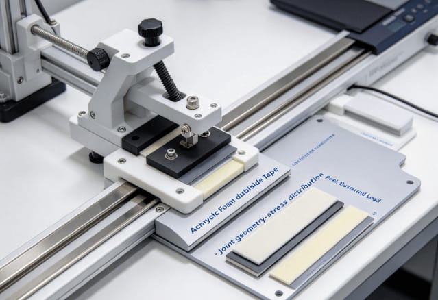
Acrylic foam double sided tape suits OEM joints that need a compliant bondline between reasonably close fitting surfaces. Choose the adhesive for the substrates and the foam thickness for the joint geometry. Then assess the sustained load at the expected service temperature.
A decorative trim strip and a projecting bracket can load the same tape very differently. The trim may mainly need contact along its length. The bracket can apply leverage that concentrates stress at an edge.
Why Joint Geometry Comes Before Adhesion Numbers
A bonded joint performs best when its geometry supports the intended load. Broad contact can distribute stress, while narrow edges can concentrate peeling forces. Increasing adhesion cannot reliably compensate for poor contact or an unsuitable load path.
Identify whether the assembly experiences sustained shear, tension, peel, or a combination. Include leverage from protruding parts. A small decorative component may create substantial edge stress when pulled during cleaning or maintenance.
The foam layer contributes compliance, but its behavior depends on formulation and construction. Do not equate every acrylic foam product with every other foam tape. A PE carrier coated with acrylic adhesive has a different architecture.
3M’s VHB design resources organize selection around substrate contact, thickness, and loading. That sequence is useful for an OEM design review. Establish the joint dimensions and movement before comparing individual product data.

Describe the complete service load
For a vertical panel, document component weight and the bonded area. Add service forces such as cable pull, cleaning pressure, or door movement. Include the highest expected bondline temperature during sustained loading.
For outdoor components, thermal movement may matter more than the room temperature hand test. Long parts can move differently from their supporting frame. Review the joint as an assembly, including constraints at corners and fasteners.
Foam Tape Thickness Selection for Uneven Surfaces
Foam tape thickness selection should follow measured surface conditions and the required finished gap. Determine whether both surfaces can contact the tape across the intended bond area. Check curvature, waviness, coatings, and localized recesses.
Measure the gap between the parts at several locations. A nominally flat cover can bow between supports, leaving the center farther from the mounting frame. The selected foam must make contact without pushing the cover outside its positional tolerance.
| Assembly condition | Selection emphasis | Useful validation |
| Flat rigid components | Controlled bondline and alignment | Thickness and contact inspection |
| Slightly uneven panels | Conformability and pressure distribution | Contact mapping on actual parts |
| Dissimilar long components | Movement within the joint | Thermal cycling and edge inspection |
| Sustained vertical loading | Creep resistance at temperature | Loaded aging and displacement checks |
| Exposed decorative joint | Color, edge finish, and stability | Appearance inspection after aging |
Compression response explains how much installation force the joint needs. A soft foam may close readily but permit unwanted movement; a firmer construction may need better surface flatness. Compare contact and final alignment using the intended fixture.

Separate three temperature questions
Application temperature describes conditions when the bond is made. Service temperature concerns the installed joint. Short exposure ratings describe a limited event under stated conditions.
Read the application and service conditions separately in 3M’s application guidance. Cold surfaces can reduce initial wetting even where a properly formed bond later tolerates colder service. For F6 grades, establish the relevant installation window from their own technical data.
For sustained loading, record displacement as well as detachment. A joint may remain attached while a cover slides enough to spoil a cosmetic gap. Set the allowed movement from the component drawing.
OEM Bonding Tape in Trim, Housings, and Panels
Acrylic foam mounting tape is often considered when visible fasteners or liquid adhesive handling complicate assembly. That choice should follow a practical comparison of joint performance and production needs. Access for pressure application is particularly important.
Appliance and equipment trim
Decorative strips may involve powder coated metal, painted surfaces, or molded plastics. Evaluate the actual coating system, including its cure and surface texture. Adhesion to bare metal does not establish adhesion to the finished panel.
Check whether the trim is rigid enough to spread installation pressure. Thin sections may bow while leaving the center poorly bonded. Fixtures or rollers should reach the full contact area without damaging the visible finish.
Electronic housings
Housing assembly can involve tight gaps and temperature variation. Review dimensional tolerance alongside bondline thickness. A tape that changes cover position may affect neighboring clips, seals, or cosmetic seams.
If electronics require low emissions, electrical properties, or flammability documentation, evaluate those requirements separately. General bonding performance does not establish compliance. Use documentation tied to the exact grade and construction.
Exterior panels and decorative parts
Outdoor joints encounter moisture, sunlight, and differential expansion. Include representative edge exposure during testing. A sealed laboratory coupon may conceal weaknesses present on an installed component.
Load critical or overhead attachments require an engineered attachment design and suitable validation. Decorative mounting examples should not become load ratings for unrelated assemblies. Use the finished product’s requirements to establish acceptance.
Establish Contact and Handling Time on the Assembly Line
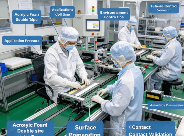
Define the production process before comparing final results. Record surface cleaning, drying, tape placement, application pressure, and elapsed time before loading. These variables can explain differences that might otherwise be blamed on material quality.
Begin with a small matrix of realistic conditions. Include the lowest planned installation temperature and the most difficult approved surface. Test startup handling as well as performance after bond development.
Useful records include:
- Exact substrate and coating identification.
- Adhesive grade, foam construction, and thickness tolerance.
- Surface preparation method and drying time.
- Application equipment and pressure control method.
- Dwell before handling, packing, and service loading.
- Environmental exposure and permitted displacement.
- Failure location, including coating or foam damage.
Inspect more than the force reading. Coating transfer, foam splitting, and edge lift reveal different problems. Photograph both separated surfaces when destructive testing is used.
F6’s foam double sided tape category includes two acrylic foam thicknesses worth comparing when the joint gap is being established:
| Construction | Published thickness excluding liner | Selection use |
| FV80 acrylic foam tape | 0.80 mm ± 0.03 mm | Assess contact where a smaller bondline is required |
| FV110 acrylic foam tape | 1.10 mm ± 0.05 mm | Assess additional compliance within the permitted assembly gap |
The thickness comparison is a starting point for fitting the joint. Adhesive compatibility and sustained loading remain separate checks. Select the grade that meets the whole assembly requirement, including position after conditioning.
FAQ
Is thicker acrylic foam mounting tape always stronger?
No. Thickness affects conformity and movement, while strength also depends on adhesive chemistry, bond area, temperature, and loading. Excess thickness can create unwanted flexibility.
Can it bond powder coated metal?
Some grades may suit specific powder coatings. Texture, surface chemistry, and coating adhesion require evaluation on the actual production finish.
Can a hand pull test confirm long term performance?
It can reveal obvious contact problems, but cannot establish sustained load behavior. Include conditioned assemblies and defined displacement or failure criteria.