
 Canada
 USA
 Japan



Tape Shear Strength Test: Read Holding Power Results

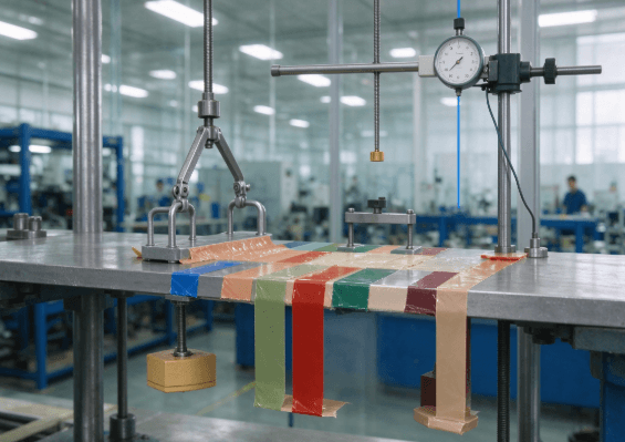
A tape shear strength test examines how a bonded specimen resists force parallel to the surface. In a static holding test, the load stays constant and the report records time, movement, or both. Dynamic shear measurements use a different loading sequence and endpoint.
Read the test arrangement before comparing the numbers. Two results can use the same tape but differ because of overlap area, temperature, dwell, or substrate. A longer holding time is meaningful only when those conditions are comparable.
What Static Shear Adhesion Measures
In a static test, a defined tape area supports a constant load under controlled conditions. The report may record time to failure or movement over a specified period. The chosen method determines the specimen arrangement and endpoint.
ASTM D3654/D3654M describes shear adhesion methods for pressure sensitive tapes. A usable report identifies the procedure and edition, then gives the specimen and loading conditions. This allows another laboratory to understand what was actually measured.
Holding time and creep answer related questions
Holding time describes how long the specimen reaches a defined endpoint under the stated load. Creep describes progressive movement while the load remains applied. A specimen can remain attached while moving too far for its application.
An assembly that supports a label may tolerate movement differently from a precision mounted sensor. The same laboratory result can therefore have different practical meanings. Interpretation requires an application specific movement criterion.
Dynamic shear is a separate measurement
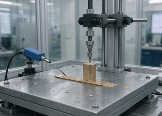
A dynamic test applies a changing force or displacement and records the material response. Results can include peak force or stress at failure. The test geometry and loading rate strongly affect interpretation.
| Measurement | Typical reported form | Main question |
| Static holding time | Time under defined load | How long does attachment persist? |
| Static creep | Displacement over time | How much does the joint move? |
| Dynamic shear | Force or stress under loading | How does the joint resist changing load? |
| Peel adhesion | Force at a defined peel geometry | How does the interface resist peeling? |
These measurements should complement each other. A tape can show high peel adhesion while moving gradually under a sustained shear load. Initial tack provides another distinct description of early contact behavior.
How to Read an Adhesive Tape Holding Power Test Report
Laboratories may describe static shear results as holding power. Look beyond that heading to the specimen details. They determine whether two reported values describe comparable experiments.
Bond area and applied load
Record both specimen width and overlap length. The resulting area influences the average stress applied to the joint. Equal hanging loads do not produce equal stress when bond areas differ.
Load must be stated clearly, including the unit and loading arrangement. A mass value describes a test weight, rather than a universal tape capacity. Avoid converting it directly into an allowable component weight.
Panel, preparation, and dwell
The substrate affects contact and failure. Standard steel can provide a repeatable laboratory reference, but it differs from textured paint, plastic, or linerboard. State whether the test used a standard panel or a production material.
Surface cleaning, application pressure, and dwell before loading also affect results. A longer dwell can allow additional contact development. Without these details, an apparent material improvement may reflect a preparation difference.
Temperature and observation period
PSA shear resistance is sensitive to the test environment. A warm test may reveal movement that is absent at room temperature. Compare results only after checking the complete conditioning and loading sequence.
A cutoff result means the observation period ended before the chosen failure endpoint was reached. It is a lower bound on survival under those conditions. Preserve the greater than notation instead of treating the cutoff as an exact failure time.
For a published example, the 3M 4492W data sheet lists static shear results with a 13 by 25 mm sample area. Its footnote states that testing stopped at 10,000 minutes. The reported loads also change with temperature, so the table cannot be read as one universal holding capacity.
Shear Testing in Mounting, Packaging, and Lamination
Static shear adhesion can help explain gradual slip in an installed tape joint. It is particularly relevant where a load remains applied for extended periods. Actual joint geometry must still be considered.
Vertical mounting
A mounted component may place much of its weight parallel to a wall or panel. However, stand off distance can also create peeling leverage. A simple laboratory shear specimen cannot reproduce every feature of that joint.
Evaluate displacement and edge lift separately. The bond may move before it detaches. A precision assembly can become unacceptable while appearing securely attached.
Packaging overlaps
Restraint tapes can experience sustained force through an overlap or an attachment to packaging. Package compression and surface tearing may contribute to failure. Distinguish these effects from adhesive creep.
Layered industrial parts
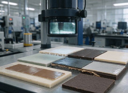
Laminated foam, felt, or polymer components may move under pressure and temperature. Movement can occur within the substrate, adhesive, or carrier. Inspect the separated layers to identify the actual location.
TheF6 product range includes constructions used for holding, mounting, and lamination. These applications illustrate different reasons for studying shear behavior. They should not be treated as evidence of a shared holding rating.
Diagnose Creep and the Location of Failure
Record what failed, rather than only when it failed. A single time value can conceal different mechanisms. Photographs and displacement observations improve interpretation.
Useful failure descriptions include:
- Adhesive release from the test substrate.
- Cohesive separation within the adhesive layer.
- Foam or carrier splitting.
- Coating lift or substrate tearing.
- Progressive slip without complete detachment.
- Specimen distortion or an invalid test arrangement.
Keep invalid results separate from valid failures. A damaged specimen or slipping fixture should not become a material performance value. Repeat work only after identifying the procedural problem.
When comparing samples, use the same procedure, panel, area, load, temperature, and dwell. Record individual results alongside any average. Large variation can be important even when the mean appears acceptable.
Two specimens can reach the same time limit while moving by different amounts. One may remain nearly stationary; the other may slip without falling. Where position matters, report creep alongside survival time.
Likewise, a short observation period can leave every specimen at the cutoff. Report that limitation instead of ranking indistinguishable results. A later comparison can use a justified endpoint suited to the measurement objective.
When one specimen fails much earlier, inspect the failure surface and preparation record. Contamination, uneven contact, or material variation can produce different patterns. Keep individual results visible so an average does not conceal the discrepancy.
For the complementary interface measurement, F6’s peel adhesion testing guide explains the separate role of peel testing. Read the two measurements together when analyzing a bonded assembly. A complete interpretation connects laboratory behavior with observed failure on real parts.
FAQ
Is a longer holding time always better?
It indicates longer survival only under comparable conditions. It does not establish removability, peel resistance, or suitability for a different joint.
Can static shear results be converted into tensile strength?
No. They describe different loading arrangements and endpoints. A holding time cannot be directly converted into a dynamic failure force.
Why can a sample pass while a component still slips?
The application may have different stress, temperature, surfaces, or leverage. The test may also permit more movement than the component can tolerate.